Insul-Tek® 250 Copper System
Preinsulated piping systems for above and below ground use on systems ranging from 350° F to 250° F.
Typical Uses:
Liquid Nitrogen
Chilled Water
CO2
Hot Water
Process Piping
Overview
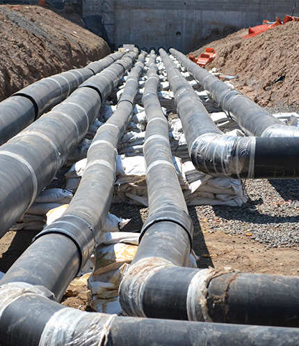
Insul-Tek® 250 Copper Systemis a totally factory fabricated, insulated and jacketed system supplied in 20' lengths. The isocyanate polyurethane foam insulation utilized in this system is the most thermally efficient type of insulation available today, making this system ideal for use on both cold and hot applications.
Preinsulated piping systems for above and below ground use on systems ranging from 350 ° F to 250 ° F.
Specification Section – Insul-Tek® 250 Copper System
General
Scope of Work
Work includes furnishing and installing factory-fabricated,
preinsulated underground copper piping systems complete with
carrier pipe, insulation, outer casing, joints, fittings, end
seals, field insulation kits, and all accessories required for a
complete operating system.
Applicable Services
- Heating hot water
- Chilled water
- Domestic hot water and recirculation
- Low-temperature process fluids
Quality Assurance
Provide preinsulated piping systems from a single manufacturer regularly engaged in the design and fabrication of factory preinsulated copper piping for a minimum of five years. System design, materials, and fabrication shall be in accordance with:
- ASTM B88 for copper tubing (Types K, L, or M as indicated).
- ASTM C591 or equivalent for polyurethane foam insulation.
- ASTM D3350 for HDPE casing, where used.
- ASTM D1784 for PVC casing, where used.
Submittals
A. Product Data:
- Manufacturer's catalog data, material descriptions, and performance characteristics.
- Rated temperature and pressure limits.
- Installation, handling, and storage instructions.
B. Shop Drawings:
- Layout of preinsulated piping, pipe sizes, routing, fittings, anchors, and expansion compensation method.
- Field joint details, end seals, manholes (if any), and transitions.
C. Certifications:
- Mill certificates for carrier pipe.
- Manufacturer's certification of insulation density and thermal conductivity.
D. Test Reports:
- Factory hydrostatic test reports for preinsulated piping.
Delivery, Storage, and Handling
Deliver pipe sections in manufacturer's original, unopened packaging with labels intact. Store pipe above grade on dunnage, off the ground, protected from standing water, mud, and direct sunlight as recommended by manufacturer. Protect ends of pipe and field joint kits from damage and moisture until installation.
Products
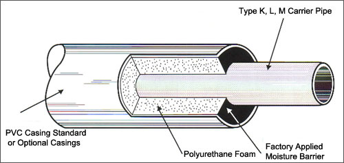
Carrier Pipe
Seamless copper water tube conforming to ASTM B88, Type K, L, or
M as scheduled on drawings. Sizes from 1/2 inch through 6 inches
nominal diameter as indicated. Joints shall be brazed or
soldered, or manufacturer's integral bronze or mechanical
couplings with elastomeric O-rings as approved. Solder shall be
lead-free; silver brazing alloys shall be used where operating
temperatures require.
Insulation
- Material: Factory-applied, rigid, closed-cell polyurethane foam.
- Minimum density: 2.0 lb/ft³ nominal.
- Closed-cell content: 90 to 95 percent minimum.
- Maximum thermal conductivity (K-factor): not greater than 0.14–0.18 BTU·in/hr·ft²·°F at 73°F.
- Temperature rating: Minimum 250°F continuous service.
Outer Casing (Jacket)
- High-density polyethylene (HDPE) meeting ASTM D3350, or Type 1, Grade 1 PVC meeting ASTM D1784.
- Thickness: Manufacturer's standard heavy-wall, suitable for direct burial and handling loads; minimum 0.060 inch for PVC jackets on small diameters.
- Casing shall be continuous around foam and bonded to insulation to provide a watertight system.
Service Ratings
- Minimum operating temperature range: 35°F to 250°F.
- Minimum operating pressure rating: 150 psig for carrier pipe and joints unless otherwise noted.
Fittings, Joints, and Accessories
Fittings (Carrier Pipe): Wrought copper fittings in accordance with ASME B16.22. Joints completed using solder or brazing compatible with design temperatures and pressures, or manufacturer's integral coupling system.
Field Joints (Insulation and Casing): Provide factory-furnished joint insulation kits consisting of split polyurethane insulation shells, outer casing sleeves (PVC or HDPE), and sealing materials. Joint kits shall be designed to match pipe casing material and provide continuity of insulation, water-tightness, and structural integrity.
End Seals and Terminators: Provide factory-fabricated end seals at all terminations, manhole entries, building wall penetrations, and changes from preinsulated to aboveground piping. End seals shall be compatible with casing material and provide a watertight barrier.
Expansion Compensation: Where utilized, provide manufacturer's engineered O-ring or integral bronze couplings designed to absorb thermal movement and limit stress on the carrier pipe without external loops or expansion devices, where permitted by manufacturer. Otherwise, provide expansion loops, offsets, or anchors as indicated on drawings.
Manholes (If Required): Prefabricated or cast-in-place manholes as indicated on drawings, sized to accommodate valves, joints, and accessories, suitable for burial depth and traffic loading indicated.
Factory Testing
Each preinsulated pipe section shall be hydrostatically tested at not less than 1.5 times design operating pressure for a minimum of one hour, or as recommended by the manufacturer.
Installation
Examination: Verify trench depth, width, and bedding conditions before installation. Do not begin work until unsatisfactory conditions have been corrected.
Trenching and Bedding: Excavate trenches to lines and grades indicated, allowing for pipe diameter, bedding, and required cover. Provide uniform, stable bedding and backfill in accordance with geotechnical recommendations and manufacturer's instructions. Avoid sharp rocks or debris that could damage casing.
Pipe Installation: Install preinsulated piping in strict accordance with manufacturer's published installation instructions and approved shop drawings. Handle pipe carefully; do not drag or drop sections. Support and align pipe to prevent sagging, misalignment, or stress on joints. Maintain required separation from other utilities and structures.
Field Joints:
- Complete carrier pipe joints (braze or solder) first; allow to cool and clean off flux before insulating.
- Clean and dry surfaces to be insulated.
- Apply insulation shells, casing sleeves, and seals per manufacturer's instructions.
- Ensure all joints are watertight and continuous with factory casing.
Anchors, Guides, and Expansion: Install anchors, guides, and expansion provisions as indicated on drawings and as required by manufacturer to control thermal movement. Ensure expansion devices or couplings are properly located and not obstructed.
Building Entries and Penetrations: Install sleeves through walls and floors with annular clearance around casing or carrier pipe per code and manufacturer. Pack annular space with mineral wool and seal both sides with an elastomeric or plastic waterproof sealant, or use mechanical seals as specified. Install end seals at all transitions from buried preinsulated sections to aboveground piping, manholes, and equipment.
Field Testing
After installation of carrier pipe and before closing all field joints, perform hydrostatic or pressure test on the system to the pressure specified on drawings, for the period specified, in accordance with manufacturer's recommendations and applicable codes. Repair leaks and defects, then retest until system is tight and accepted.
Backfilling
After testing and inspection, backfill trench with approved material in lifts, compacted to the density specified. Maintain minimum cover indicated on drawings. Protect casing from direct contact with large stones or sharp objects. Provide plastic marker tape above piping at depth indicated on drawings.